 EN
EN


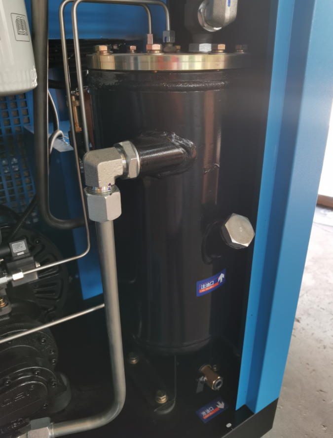
The 4‑AM Shutdown – When an Oil Leak Stopped the Production Line
A food packaging plant in the Midwest lost an entire production shift when their 200‑hp rotary screw compressor shut down on a low‑oil alarm at 4 AM. The maintenance team discovered oil pooled around the airend shaft seal—a slow leak that had been ignored for weeks. The seal had failed due to misalignment between the motor and airend, causing excessive runout. The repair required a new shaft seal, a wear sleeve, and realignment—costing $4,200 in emergency parts and labor, plus $8,000 in lost production. The leak had started small. A simple alignment check six months earlier would have cost $200 and taken 30 minutes.
This scenario is more common than most plant engineers admit. Over the past six years, maintenance consultants have observed that early diagnosis of oil leakage consistently prevents costly compressor failures and production downtime. Understanding how to identify and diagnose oil leaks isn't just about troubleshooting; it is about protecting production uptime and extending equipment life.
Worn Seals and Gaskets – Visual and Operational Red Flags
Visual inspection is the first line of defense. Look for oil sheen, wet grime, or dripping at the airend flange gaskets and the oil separator tank's lid or drain connections. Operational red flags include a steady drop in oil level despite no external pool, activation of the low‑oil alarm, and rising air discharge temperature.
| Warning Sign | What to Check | Action Required |
|---|---|---|
| Oil sheen on gaskets | Airend flange, separator lid | Tighten or replace gaskets |
| Steady oil level drop | No visible external leak | Inspect separator and seals |
| Low‑oil alarm | Oil level sensor | Check for internal leakage |
| Rising discharge temp | Cooling system, oil quality | Investigate separator condition |
At the oil separator, a degraded gasket between the element and housing can allow oil mist to escape—often visible as dampness around the clamp ring—and may cause internal bypass, increasing oil carryover and downstream filter saturation. Industry maintenance data (2023) shows that improperly torqued gaskets and thermal cycling cause over 35% of all oil‑leak incidents in rotary screw compressors. A quarterly inspection of all gasket interfaces—especially after seasonal temperature swings—helps detect early embrittlement before catastrophic failure.
Shaft Seal Failure – Torque, Alignment, and OEM Compatibility
Drive shaft seal leakage is commonly caused by over‑torquing during installation, misalignment between motor and airend, or use of non‑OEM seals with incorrect material hardness. Symptoms include oil leaking at the shaft entry—most pronounced during startup.
| Cause | Symptom | Corrective Action |
|---|---|---|
| Over‑torquing | Seal distortion, uneven wear | Follow OEM torque spec (18–25 N·m) |
| Misalignment | Leak at shaft entry | Align to <0.05 mm TIR |
| Non‑OEM seals | Premature failure (<500 hrs) | Use OEM‑specified lip seals |
| Grooved shaft sleeve | Oil bypass | Measure Ra <0.4 µm; install wear sleeve |
Diagnosis requires checking coupling alignment to within 0.05 mm TIR using a laser or dial indicator, and verifying gland nut torque per OEM specifications (typically 18–25 N·m for small compressors). Always use OEM‑specified lip seals to ensure correct interference fit and temperature resistance. Reusing grooved shaft sleeves is a frequent error; measure shaft surface roughness (Ra < 0.4 µm), and install a wear sleeve if pitting is present. Non‑OEM seals may fail within 500 hours due to compound mismatch. Proactive alignment and torque validation can extend seal life to over 20,000 hours.
Oil Separator Degradation – Lifespan, Contamination, and Replacement
The oil separator element in a typical rotary screw compressor is designed for 6,000–8,000 hours of service. Degradation beyond this window commonly stems from particulate contamination in inlet air, use of non‑compatible lubricants that degrade coalescing media, or sustained operation at excessive temperatures.
| Issue | Indicator | Solution |
|---|---|---|
| Clogged separator | Pressure drop >0.7 bar | Replace element immediately |
| Oil carryover | Wet downstream air lines | Inspect and replace separator |
| Varnish buildup | Lab oil analysis (acidity) | Change oil; inspect separator |
| Wrong lubricant | Coalescing media degradation | Use OEM‑specified oil |
When clogged or saturated, the element allows sharp increases in oil carryover—contaminating downstream air lines and tools. Monitor differential pressure across the separator housing: once it exceeds the manufacturer's limit (commonly 0.7–1.0 bar), replace the element immediately with the correct OEM‑specified part. Before replacement, isolate and depressurise the unit, drain residual oil, and torque housing bolts to the recommended value to prevent new leaks. Annual laboratory oil analysis helps detect early varnish or acidity—key indicators that oil chemistry is accelerating separator wear.
Oil Scavenge Line Blockage – Pressure Differential and Safe Cleaning
A blocked oil scavenge line prevents separated oil from returning to the sump, causing oil to accumulate inside the separator and pass into the air stream. The primary indicator is a rising differential pressure across the separator element—any steady reading above 0.7 bar warrants immediate inspection.
| Symptom | Likely Cause | Action |
|---|---|---|
| ΔP >0.7 bar | Scavenge line blockage | Inspect and clean line |
| Oil in discharge air | Separator flooding | Clear scavenge line; check check valve |
| Slow pressure build | Restricted return | Flush with compatible solvent |
To clean safely, shut down and isolate the separator tank. Disconnect the scavenge line at both ends and flush it with a low‑pressure solvent compatible with the compressor oil. Never use compressed air, as it risks damaging the check valve or forcing debris deeper into the system. After cleaning, verify full internal clearance and reinstall using new sealant on threaded connections. Perform a static pressure test and monitor differential pressure during the first hour of operation to confirm resolution.
Air Leak Detection – Ultrasonic and Soapy Water Testing
Undetected air leaks waste 30–50% of compressed air in typical systems—and up to 80% in poorly maintained installations (Compressed Air Best Practices, 2022).
| Detection Method | Best Application | Advantage |
|---|---|---|
| Ultrasonic detector | Noisy plant environments | Rapid scanning; pinpoints leaks |
| Acoustic imaging | Extensive piping networks | Live video overlay; fast surveys |
| Soapy water test | Joints, fittings, quick disconnects | Low‑cost; confirms pinhole leaks |
| Combination approach | Routine maintenance | Scan then confirm; thorough coverage |
Ultrasonic leak detectors capture high‑frequency hissing sounds imperceptible to the human ear. Advanced acoustic imaging models overlay leak locations onto live video feeds, dramatically speeding up surveys of extensive piping networks. Soapy‑water testing remains a trusted, low‑cost method: applying a solution with a paintbrush to joints, fittings, couplings, and quick disconnects reveals even pinhole leaks via bubble formation. Common leak‑prone zones include hoses, FRL assemblies, condensate traps, and flange gaskets.
Torque Validation – Preventing Joint‑Related Leakage per ISO 8573‑1
Maintaining air purity to ISO 8573‑1 Class 2 standards (e.g., particles ≤0.1 mg/m³, pressure dewpoint –40°C) demands a leak‑free system. Joint‑related leakage most often originates from incorrect torque: under‑tightened compression, flare, or threaded connections permit micro‑escapes under pressure, while over‑tightening can crack threads or crush gaskets—creating new leak paths.
| Torque Issue | Consequence | Prevention |
|---|---|---|
| Under‑tightened | Micro‑leaks under pressure | Use calibrated torque wrench |
| Over‑tightened | Cracked threads; crushed gaskets | Follow OEM specifications |
| Thermal loosening | Leaks after temperature swings | Regular torque audit schedule |
| Post‑maintenance | New leak paths | Re‑torque all fittings |
A calibrated torque wrench set to the manufacturer's specification eliminates guesswork. Validation should cover every fitting, flange bolt, and union in the distribution network—especially after maintenance or temperature swings that loosen connections. Factories adhering to a regular torque audit schedule report up to 60% fewer fitting leaks.
Minimum Pressure Valve Malfunction – Symptoms and Troubleshooting
The minimum pressure valve (MPV) ensures rapid oil circulation during startup and maintains internal pressure above atmospheric level. When the MPV malfunctions, the most telling symptom is high internal sump pressure with little or no air delivered downstream.
| Symptom | Likely Cause | Solution |
|---|---|---|
| High sump pressure, low delivery | Stuck or poorly sealing valve | Clean or replace MPV |
| Frequent load/unload cycling | Spring fatigue or carbon deposits | Disassemble and clean annually |
| Oil carryover to air lines | Oil bypass through MPV | Replace MPV assembly |
| Pressure drop >0.3 bar (unloaded) | Valve wear | Replace entire MPV assembly |
Field experience shows that quarterly disassembly and cleaning, combined with annual rebuild kit replacement, significantly reduces unscheduled downtime. During inspection, verify spring tension meets OEM specs and that the poppet seat is free of pitting. If a pressure drop test across the valve exceeds 0.3 bar while the compressor runs unloaded, replace the entire MPV assembly. Prompt attention prevents cascading failures in the separator element and downstream filtration.
Quality and Service – The BXKM Commitment
Achieving reliable compressor performance requires more than reactive repairs—it demands a systematic approach to maintenance, alignment, and component quality. BXKM's engineering expertise in auxiliary equipment for industrial processing supports the reliability of compressor systems through supply of precision components and aftermarket service. By providing high‑quality replacement parts, gaskets, and filtration components backed by rigorous quality control, BXKM helps maintenance teams reduce downtime and extend equipment life. This comprehensive support, combined with a responsive supply chain, ensures that critical replacement parts are available when needed—keeping production lines running.
FAQ
| Question | Answer |
|---|---|
| What are the main symptoms of oil leakage in screw compressors? | Steady oil level drops, low‑oil alarms, rising discharge temperature, and visible oil dampness around gaskets or shaft seals. |
| Why is OEM specification important for seal replacement? | OEM parts ensure correct material hardness, interference fit, and temperature resistance—preventing premature failure. |
| How can I detect air leaks in a compressed air system? | Use ultrasonic detectors for high‑frequency sounds or soapy water testing for visible bubbles at joints and fittings. |
| What causes oil separator degradation? | Particulate contamination, non‑compatible lubricants, high operating temperatures, or exceeding the 6,000–8,000 hour service life. |
| What are the signs of minimum pressure valve malfunction? | High sump pressure, reduced air delivery, frequent cycling, and excessive oil carryover into air lines. |
| How can torque issues be prevented? | Use a calibrated torque wrench set to OEM specifications and conduct regular torque audits—especially after maintenance or temperature changes. |